Updated 2026-07-21
This is the digital manual for Ferroamp´s home system. For product manual see the Installation guide.
For support and information about operation of the Ferroamp system see “Support for installers”
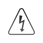
The lightning symbol within a triangle warns of dangerous electrical voltage.
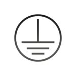
A vertical line and three horizontal lines in a circle indicate earth connection terminal.
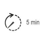
The product contains charged capacitors. Wait at least 5 minutes after disconnecting the product before handling it.
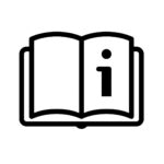
An open book indicates that the manual should be consulted during installation.
The symbol indicates that the product must not be thrown away in household waste but should be recycled as electrical waste.
For input on how to improve this digital manual send an email to: improve@ferroamp.se.
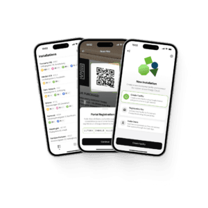
You need to download Ferroamp‘s installer app to be able to register and commission the system, this app can be downloaded at the following links:


To install and register a system, you as an installer need an installer account in Ferroamp‘s portal EnergyCloud.
You can create this by going to the following link: https://portal.ferroamp.com/ or pressing “Register“ in the APP.
If you already have an installer account, go ahead and skip this section.
If you don´t have an installer account, follow the guide below:
It is important to read through the manuals for the products you are going to install before starting installation. You can find the latest version of all our documentation under Downloads.
The manual for EnergyHub Wall 14 kW is only available digitally and not as a physical sheet in the box. You can download it directly here.

Please note that it is important to have a safety distance around the products in order for the installation to be safe and to maintain warranty. The products are mounted using wall brackets. Ensure that safety distances are maintained before screwing in the wall brackets.
Safety distances:
EnergyHub:
Over: 200 mm
Under: 100 mm
Sides: 100 mm
SSO
Over: 200 mm
Under: 200 mm
Sides: 50 mm
ESO
Over: 200 mm
Under: 200 mm
Sides: 50 mm
For more information regarding safety distances, please read the manual for each product under Downloads.
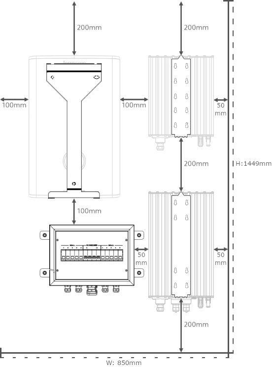
Example installation.
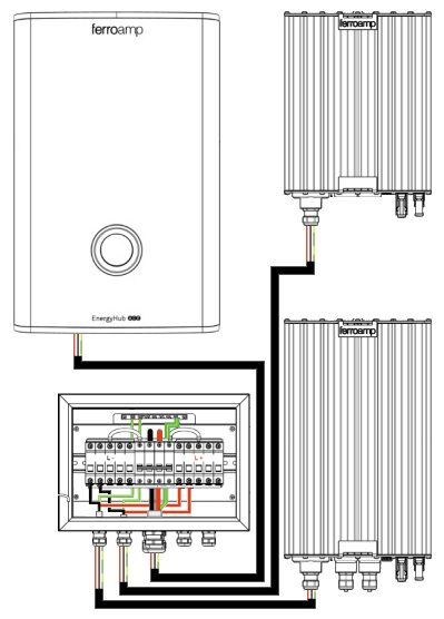
The units are linked together via +, – and PE. In this case, we have used our Power Distribution Box 5 as the interconnection box in the system. The EnergyHub connects to the top of the 63 A MCB in the middle of the cabinet, SSOs/ESOs connect to the fuse holders at the bottom edge of the DIN rail. Ferroamp recommends that multi-stranded cable with ferrules is always used in the DC grid.
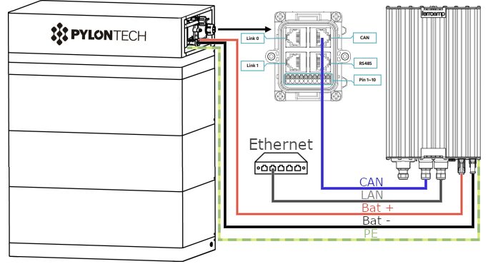
Connect +, – and PE from the BMS to ESO15.
The ESO 15 kW comes with MC4 connectors for + and – with PE from the battery BMS that can be connected to the ground points in the chassis of the ESO 15 kW or to a separate earth terminal.
The ESO 15 kW also comes with a CAN communication cable, RJ45, to the I/O port. This is pre-thermenated for Pylontech’s CAN pinout and may need to be changed for other battery manufacturers.
For the communication to work, it is important that this is connected in the “CAN” port in the BMS.
The ESO15 kW needs to be connected to the same network as the EnergyHub, this is most easily done with a switch where the incoming network, EnergyHub and ESO 15 kW are connected.
For more information, see Communication/CT.
Ferroamp also recommends connecting the battery to Pylontech’s own cloud service “Solarman”.
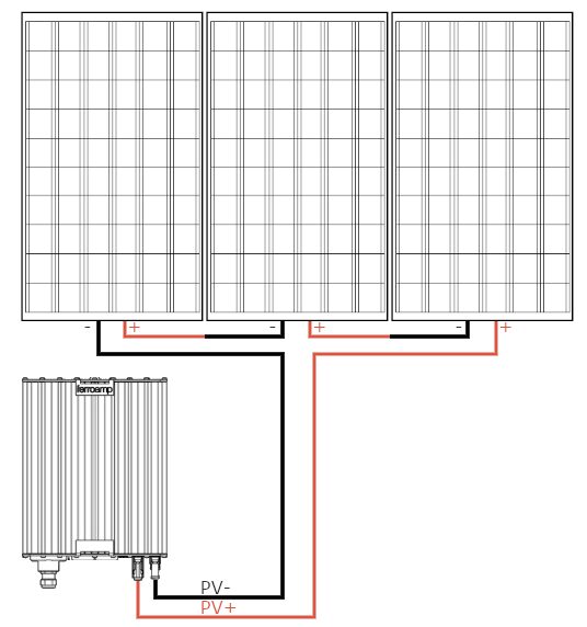
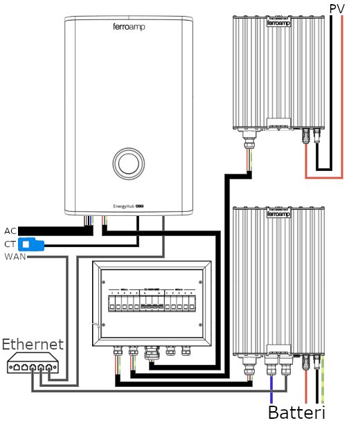
EnergyHub, ESO 15 kW and the customer‘s network connection (incoming network) need to be in the same switch/router for the communication to work. The ESO 6 kW communicates via PLC over the DC grid and does not require an external communication cable between the EnergyHub and Powercase.
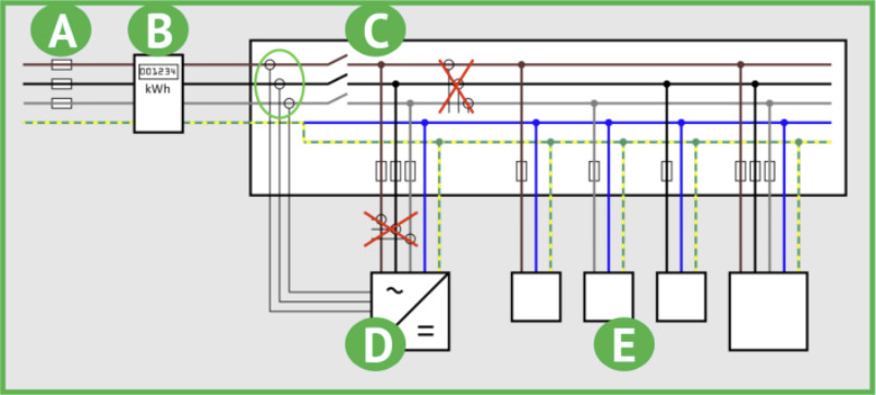
It is important that the CT clamps are located directly after the electricity meter between (B) and (C) and measure all load in the property if EnergyHub is installed with the function of phase balancing to lower the main fuse in the property.
The current transformers should not be located between (C) and (D) on EnergyHub’s supply cable, or between (C) and (E) on the property’s consumers.
Create a new system:
Then tap “Continue” to proceed to “Digital Self Audit”.
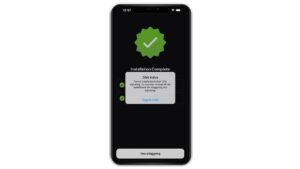
Click on the “Open DSA” button:
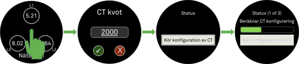
If the system shows as “Offline” in the DSA, or the system has lost its connection to the internet and shows offline in the app, check the following:
Plugging a computer into the same port that the EnergyHub is connected to is a good way to see if you are getting out on the internet.
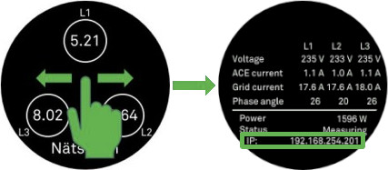
By swiping on the display, you can also check if EnergyHub has an assigned IP address. If the system displays “xx.xx.xx.xx“, EnergyHub does not receive an assigned IP address from the router.
If the system shows that the EnergyHub is running the wrong software version (EhubOS Version) create a ticket with Ferroamp Support for guidance.
Important! Before disconnecting DC cabling, connectors or DC fuses, the EnergyHub must be switched off and the conding bank in the system must be discharged.
Always check before pulling out a plug, removing a fuse, plugging in a plug, or screwing on a terminal to ensure that the system is de-energized.
In Ferroamp’s Power Distribution Box and ESS Powercase, there are DC fuses in the system to protect cables and devices in the DC grid. These are equipped with 32A fuse holders and 15A fuses from the factory.
It is possible to open the fuse holder and replace the fuse. Max 32A fuse in this fuse holder.
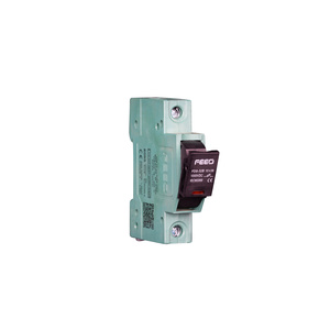
If a unit (SSO/ESO) has lost contact with the EnergyHub during operation and the LED is not lit, a good first step is to check the DC fuses.
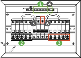
Important! Before disconnecting DC cabling, connectors or DC fuses, the EnergyHub must be switched off and the conding bank in the system must be discharged.
Always check before pulling out a plug, removing a fuse, plugging in a plug, or screwing on a terminal to ensure that the system is de-energized.
If all installed components of the DSA, step 4 shows red follow the steps below:
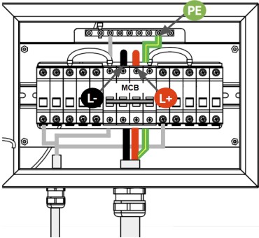
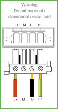
Before you begin troubleshooting DC cabling and plugging in devices to the DC network. Start by checking that the fuse is intact according to Troubleshooting: Fuses above.
Important! Before disconnecting DC cabling, connectors or DC fuses, the EnergyHub must be switched off and the conding bank in the system must be discharged.
Always check before pulling out a plug, removing a fuse, plugging in a plug, or screwing on a terminal to ensure that the system is de-energized.
If one or more SSOs in DSA, step 4 shows red follow the steps below:
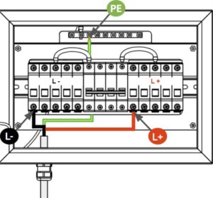
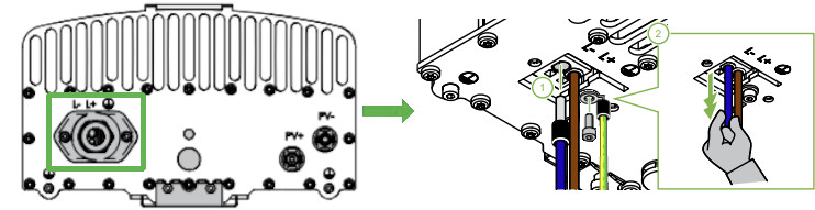
Important! Before disconnecting DC cabling, connectors or DC fuses, the EnergyHub must be switched off and the conding bank in the system must be discharged.
Always check before pulling out a plug, removing a fuse, plugging in a plug, or screwing on a terminal to ensure that the system is de-energized.
If the battery in DSA, step 4 shows red follow the steps below:
Troubleshooting DC
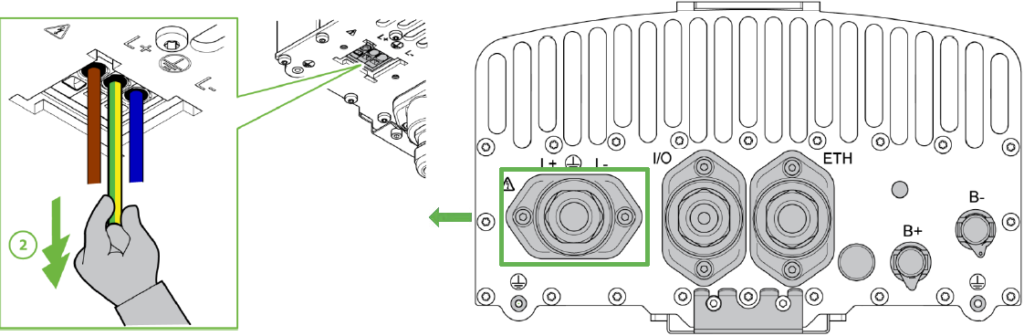
Troubleshooting ETH – EnergyHub:
If the EnergyHub is online but ESO cannot connect with the EnergyHub and displays 8 pulses on the LED. And that you got a red box over “Batteries” in DSA:
Troubleshooting I/O – CAN:
If ESO makes contact with the EnergyHub but does not register a battery, ESO displays 4 pulses on the LED. This also causes the DSA to report red over “Batteries”.
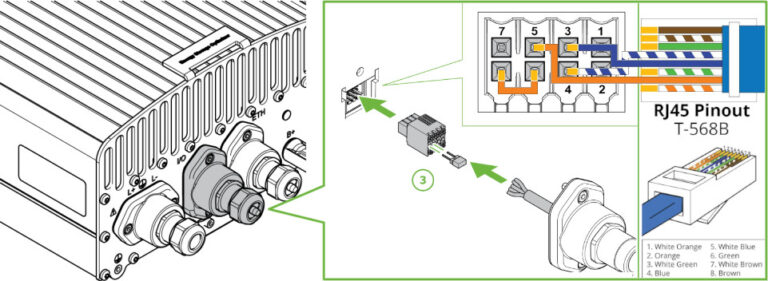
Note! The described CAN-pinout above is for connection to Pylontech’s BMS. When connected to other batteries, the Pinout to ESO I/O port may vary.
The jumper that bridges the interlock function (Pin: 8 and 6) in the connector should sit against the wall of the included I/O to CAN cable.
For information about warranty and extended warranty options, see Downloads.